As I’ve been migrating this blog to AWS a particular annoyance I’ve been experiencing is that whenever I want to deploy the application to Elastic Beanstalk (EB) I need to make a backup of the production data and bundle it with the source code that gets deployed. This is due to the way the database currently fits into the solution architecture—as a service running inside a Docker container on the same EC2 instance as the application. Given that an EB deployment creates a new EC2 instance as opposed to mutating an existing one, this essentially means that the production data is lost every time an EC2 instance is terminated (via EB environment termination). This has made creating the backup a necessary prerequisite for a deployment.
All of which brings me to the subject of this post: decoupling the database from the application by migrating the database to RDS, AWS’s main relational-database offering. RDS is compatible with several popular database technologies, including MySQL—the one used by this blog. The general idea is that RDS manages the database for you as opposed to you managing it yourself, for example via Docker on EC2 as I am doing. Once the RDS database is established, all you have to do is configure your application, in my case this blog, to point at the RDS instance. And because the RDS instance is hosted outside the scope of the EB environment, deployments to the EB environment should no longer result in data being lost.
In this post I’ll discuss the steps I took to migrate this blog’s database to RDS, which were broadly as follows:
- Creating security groups for EB and RDS
- Creating the RDS database
- Testing the connection to the RDS database
- Updating source code to integrate with the new database
- Migrating data from the old database to the new database
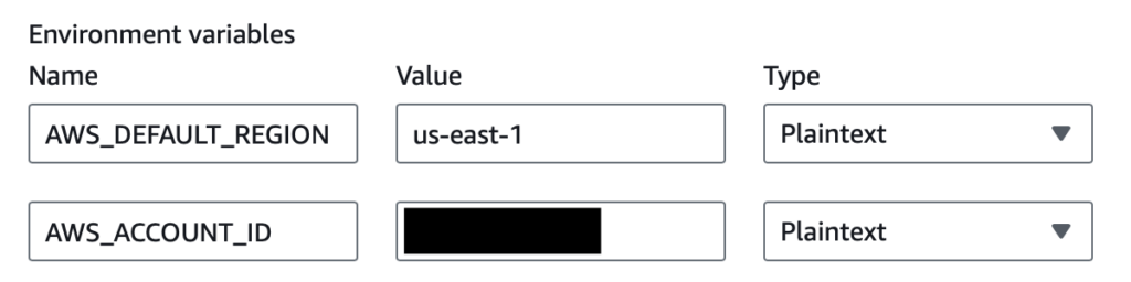
Many of the steps assume the use of the AWS CLI. The CLI commands assume the presence of a specific profile, which in my case is named “blog,” in an .aws/credentials file.
Creating security groups for EB and RDS
Security groups are needed to enable communication between the EB environment and the RDS database. Creating a functioning security group is a two-step process:
- Creating the security group itself
- Creating the security-group rules that are needed to manage network traffic
Creating a security group can be achieved with the aws ec2 create-security-group command:
aws ec2 create-security-group \
  --group-name <group_name> \
  --description <description> \
  --vpc-id <vpc_id> \
  --profile <profile>
Creating a security-group rule can be achieved with the aws ec2 authorize-security-group-<egress|ingress> command:
aws ec2 authorize-security-group-<egress|ingress> \
    --group-id <group_od> \
    --protocol <protocol> \
    --port <port> \
    --source-group <source_group> \
    --profile <profile>
Creating the security groups
I created the security group for EB as follows:
aws ec2 create-security-group \
    --group-name EBSecurityGroup \
    --description "Enables EB to send traffic to RDS" \
    --vpc-id <vpc_id> \
    --profile blog
And the security group for RDS as follows:
aws ec2 create-security-group \
    --group-name RDSSecurityGroup \
    --description "Enables RDS to receive traffic from EB" \
    --vpc-id <vpc_id> \
    --profile blog
In both cases <vpc_id> corresponded to the ID of the VPC in which the EB environment and RDS database would be located.
Upon success the commands returned a JSON response containing the ID of the security group that was created:
{
    "GroupId": <groupId> // e.g., "sg-1234567890abcdef1"
}
These IDs would be needed in the next step: creating the security-group rules.
Creating the security-group rules
In my case I needed to add an outbound rule to the EB security group and an inbound rule to the RDS security group. The EB security group’s outbound rule enables traffic to flow from the EB environment to the RDS database; the RDS security group’s inbound rule enables traffic to flow to the RDS database from the EB environment.
I created the EB security group’s outbound rule as follows:
aws ec2 authorize-security-group-egress \
    --group-id <eb_group_id> \
    --protocol tcp \
    --port 3306 \
    --source-group <rds_group_id> \
    --profile blog
And the RDS security group’s inbound rule as follows:
aws ec2 authorize-security-group-ingress \
    --group-id <rds_group_id> \
    --protocol tcp \
    --port 3306 \
    --source-group <eb_group_id> \
    --profile blog
Note how the egress command’s group-id is the ingress command’s source-group and vice versa.
Upon success the commands returned a JSON response resembling the following:
{
    "Return": true,
    "SecurityGroupRules": [
        {
            "SecurityGroupRuleId": <security_group_rule_id>,
            "GroupId": <group_id>,
            "GroupOwnerId": <group_owner_id>,
            "IsEgress": <is_egress>,
            "IpProtocol": "tcp",
            "FromPort": 3306,
            "ToPort": 3306,
            "ReferencedGroupInfo": {
                "GroupId": <group_id>,
                "UserId": <user_id>
            }
        }
    ]
}
With the security groups created I was able to move on to creating the RDS database itself. For this I used the AWS Console.
Creating the RDS database
To create the database I went to Aurora and RDS > Databases > Create database in the AWS Console and completed the steps of the database-creation wizard as follows.
Choose a database creation method
- Standard create
Engine options
- Engine type: MySQL
- Engine version: 8.0.42
Templates
- Free tier
Settings
- DB instance identfier: wordpress
- Credential settings
- Master username: <username>
- Master password: <password>
Instance configuration
- DB instance class:
- Burstable classes:
- db.t3.micro
- Burstable classes:
Connectivity
- Virtual private cloud (VPC): <vpc_id>
- VPC security group (firewall): RDS Security Group
- Availability Zone: <availability_zone>
After completing the steps I clicked “Create database” and waited for the database to be created—this took several minutes. Upon creation of the database I went to the database detail page and retrieved the RDS endpoint:
<db_instance_identifier>.<unique_id>.<availability_zone>.rds.amazonaws.comI found the specific endpoint under Connectivity & security > Endpoint & port.
With this information in hand I was able to move on to testing the connection to the RDS database.
Testing the connection to the RDS database
The basic means I chose of testing the connection to the RDS database was to create an EC2 instance in the EB environment’s security group and then attempt to connect to the database from that EC2 instance. A successful connection would indicate that the security groups and database had been created and configured correctly. The main steps involved in actually setting up and performing the test were as follows:
- Launching the EC2 instance
- Connecting to the EC2 instance
- Testing the connection to the RDS database
Launching the EC2 instance
To launch the EC2 instance I first created a key pair and then launched the instance using that key pair.
I created the key pair as follows:
aws ec2 create-key-pair \
    --key-name <key_name> \
    --query "KeyMaterial" \
    --output text > <key_name>.pem \
    --profile blog
The output of this command was a <key_name>.pem file containing a private key.
I then launched the EC2 instance as follows:
aws ec2 run-instances \
    --image-id <image_id> \
    --instance-type t2.micro \
    --key-name <key_name> \
    --security-group-ids <eb_security_group_id> \
    --subnet-id <subnet-id> \
    --associate-public-ip-address \
    --profile blog
Some notes on the arguments passed to this command:
- image_id corresponded to the ID of an AMI in the AWS Free Tier.
- key-name corresponded to the name of the key pair created previously.
- security-group-ids corresponded to the ID of the EB environment’s security group.
- subnet-id corresponded to the ID of a subnet within the EB environment’s VPC.
- associate-public-ip-address was included to make the EC2 instance accessible from the internet, which would be needed for my test.
Connecting to the EC2 instance
Connecting to the EC2 instance involved the following steps:
- Finding my IP address
- Enabling the EC2 instance to receive traffic from my IP address
- Finding the public IP address of the EC2 instance
- Connecting to the EC2 instance
I found my IP address using the following cURL command:
curl -4 ifconfig.meI then enabled the EC2 instance to receive traffic from my IP address using aws ec2 authorize-security-group-ingress:
aws ec2 authorize-security-group-ingress \
    --group-id <group_id> \
    --protocol tcp \
    --port 22 \
    --cidr <ip_address>/32 \
    --profile blog
Here, <group_id> referred to the ID of the EB environment’s security group.
I then found the public IP address of the EC2 instance. At the time I used the AWS Console for this; however I believe I could have used aws ec2 describe-instances as follows:
aws ec2 describe-instances \
    --instance-ids <instance_id> \
    --query "Reservations[0].Instances[0].PublicIpAddress" \
    --output text \
    --profile blog
Here, <instance_id> referred to the ID of the launched EC2 instance.
I then connected to the EC2 instance using ssh:
ssh -I "<key_name>.pem" ec2-user@ec2-<hyphen_separated_public_ip_address>.compute-1.amazonaws.comASCII art indicated a successful connection:
   ,     #_
   ~\_  ####_        Amazon Linux 2023
  ~~  \_#####\
  ~~     \###|
  ~~       \#/ ___   https://aws.amazon.com/linux/amazon-linux-2023
   ~~       V~' '->
    ~~~         /
      ~~._.   _/
         _/ _/
       _/m/'
Testing the connection to the RDS database
To test the connection to the RDS database I used the telnet utility to send a request to the RDS endpoint. Given my chosen AMI did not bundle telnet I had to install it with yum:
sudo yum install -y telnetI was then able to make the request to the RDS endpoint:
telnet <rds_endpoint> 3306The following output signified a successful connection:
Connected to wordpress.cynw64si07wk.us-east-1.rds.amazonaws.com.
Escape character is '^]'.
J
8.0.43%%R!f]�~qN'^WxylJ-mysql_native_password2#08S01Got timeout reading communication packetsConnection closed by foreign host.
(I believe the timeout was expected given I was using telnet to hit the endpoint instead of a dedicated MySQL client.)
After testing the connection I was in a position to update my blog’s source code for the integration with the RDS database.
Updating source code to integrate with the new database
Updating my blog’s source code for RDS integration involved a couple of minor changes to the EB environment’s config and WordPress application’s config.
For the EB environment’s config, all I had to do was update the launch config for the environment. This is stored in an .ebextensions file containing option_settings for the environment. The only change to this file was to add the SecurityGroups setting under aws:autoscaling:launchconfiguration:
option_settings:
  ...
  aws:autoscaling:launchconfiguration:
    ...
    SecurityGroups: <eb_security_group_id>
  ...
For the WordPress application’s config, all I had to do was to update the DB_HOST environment variable in the Docker env file for the production environment:
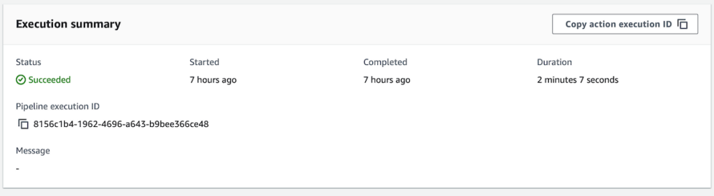
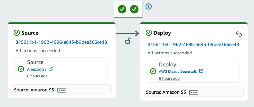
DB_HOST=<rds_endpoint>After making these code changes I performed a deployment so that I would have a staging environment from which I could connect to the RDS database via mysql. This was for the purpose of migrating data to the new database.
Migrating data from the old database to the new database
Migrating data from the old database to the new database involved exporting the data from my live environment’s database (native MySQL) and importing it to my staging environment’s database (RDS MySQL). Given the idiosyncrasies of my solution architecture, there were some specifics to the process I ended up following, which were as follows (comments precede commands).
Exporting data from the old database
// create a container session
sudo docker exec -ti <container_id> bash
// navigate to the container's home directory
cd /home
// export the data from the old database
mysqldump -u <user> -p --all-databases=true > backup.sql
// exit the container session
exit
// navigate to the host's home directory
cd /home
// copy the exported data from the container to the host
sudo docker cp <container_id>:/home/backup.sql .
// upload the exported data to S3
aws s3 cp backup.sql s3://<bucket_name>/backup.sql
Importing data to the new database
// navigate to the host's home directory
cd /home
// download the exported data from S3
sudo aws s3 cp s3://<bucket_name>/backup.sql .
// copy the exported data from host to container
sudo docker cp backup.sql <container_id>:/home
// create a container session
sudo docker exec -ti <container_id> bash
// navigate to the container's home directory
cd home
// import the exported data to the new database
mysql -h <rds_endpoint> -P 3306 -u <user> -p < backup.sql --force
The only step of the export–import process that was in any way bothersome was the very last one: importing the exported data to the new database. I kept running into permissions errors when running the mysql command without the –force flag. I didn’t have any success trying documented solutions/workarounds to the errors and so in the end I opted for the brute-force approach. For the time being I’m assuming said approach to be harmless given that manual testing of the WordPress application didn’t reveal any obvious problems.
Wrapping up
After completing all of the above steps I was left with a decoupled application and database. All that remained was for me to remove the MySQL service configuration in my production Docker Compose files and perform one more deployment to test the changes. After the deployment I confirmed (via docker ps) that the EC2 instance for the EB environment was no longer running a container for the MySQL database and (via WordPress Site Health Info) that the WordPress application was pointing at the RDS database.